

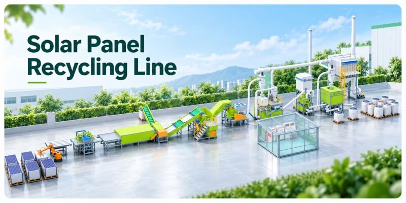




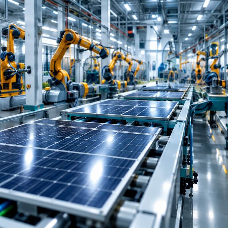








As mixed PV waste volumes grow, recyclers must recover more silicon from increasingly varied panel structures. Single-glass and double-glass modules respond differently during delamination, crushing, and separation. Therefore, one fixed process can create excess fines, glass carryover, and unstable silicon purity. This FAQ explains how industrial projects can improve silicon recovery through feed control, thermal treatment, particle sizing, and staged separation. It also identifies the equipment needed for a bankable mixed-panel recycling line.
How Can Feedstock Zoning Stabilize Silicon Recovery?
Mixed modules create unstable silicon recovery because glass mass, polymer structure, and panel thickness vary. Therefore, the line should separate feedstock before thermal treatment. Controlled feed zones then stabilize loading, residence time, and downstream product quality.
How Can you Increase Silicon Recovery from Mixed Solar Panels
Daily tonnage alone cannot define a mixed-panel project. A 16-ton batch may contain about 800 single-glass panels or 500 double-glass panels. Therefore, equal weight can create different loading volumes and heat demand. Project engineers should define each feedstock group before configuring the production line.
| Feedstock data | Process impact | Recommended line configuration |
| Single-glass and double-glass ratio | Changes glass and polymer content | Separate feed buffers |
| Average panel weight | Determines actual panel quantity | Weighing conveyor |
| Glass thickness and module size | Changes loading density | Panel inspection conveyor |
| EVA, POE, and backsheet structure | Changes delamination behavior | Dedicated operating recipe |
| Complete, broken, or rejected panels | Changes fines generation | Controlled feeding route |
| Frame and junction-box condition | Changes pretreatment workload | Frame and junction-box removal equipment |
Double-glass panels usually contain more glass. Moreover, two glass layers enclose the silicon cells. Therefore, the line needs stable loading before thermal delamination begins. Solar panel frame removal machines can recover aluminum before feeding. Meanwhile, junction-box removal equipment can reduce copper and plastic contamination. Inspection and weighing conveyors then direct each panel group into the correct buffer.
How Can you Increase Silicon Recovery from Mixed Solar Panels
Single-glass and double-glass panels should not use one fixed operating recipe. Their different structures create different heating, cooling, and material-release behavior. The PLC can store feeding speed, residence time, heating curve, negative pressure, cooling speed, and screening settings. Therefore, operators can change panel recipes without rebuilding every parameter manually.
| PLC setting | Main control purpose |
| Feeding speed | Stabilizes material loading |
| Residence time | Supports complete layer release |
| Heating curve | Matches different panel structures |
| Negative pressure | Controls gas movement and leakage |
| Cooling speed | Protects silicon from excessive breakage |
| Screening settings | Matches the final particle distribution |
Stable recipes reduce incomplete delamination and excessive silicon breakage. However, higher settings do not always improve recovery. The correct recipe should balance layer release, silicon integrity, and continuous production stability.
How Should a Thermal Release System Preserve Silicon Before Separation?
Silicon recovery depends on how gently the line releases each laminated layer. Aggressive crushing creates glass-rich fines and carries silicon into reject streams. Therefore, the process should loosen EVA and backsheets before strong mechanical force. This thermal route protects larger silicon fragments and reduces downstream separation pressure.
Release Bonded Layers Within a Stable Thermal Window
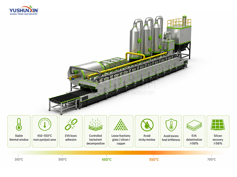
The furnace should separate bonded layers, not grind solids through heat. EVA must lose adhesion, while backsheets must complete controlled decomposition. Meanwhile, glass, silicon cells, and copper ribbons should leave as loose fractions. Internal process data places the main pyrolysis zone between 450°C and 550°C. However, panel structure, thickness, and feed rate still determine the final setting. Low temperatures leave sticky residues. Conversely, excessive heat increases silicon brittleness, carbon attachment, and fine-particle formation. Therefore, buyers should judge the furnace through delamination quality, not maximum temperature. Tunnel-furnace specification targets at least 99% EVA delamination and 98% silicon recovery.
Balance Heat Across Mixed Panel Structures
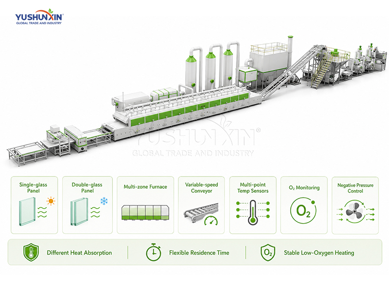
Single-glass and double-glass panels absorb heat differently. Double-glass modules contain another glass layer, so their core temperature rises more slowly. Therefore, one fixed residence time can underprocess some panels and overheat others. A multi-zone tunnel furnace gives each stage a separate thermal duty. Variable-speed conveying then adjusts residence time without interrupting production. Multi-point temperature sensors track the actual heating profile across the furnace. Oxygen monitoring and negative-pressure control also stabilize the low-oxygen environment. Together, these controls reduce production variation and protect silicon quality. The tunnel process can also match conveyor speed with different panel structures.
Lower Material Temperature Before Size Reduction
The line should not crush material immediately after pyrolysis. Hot glass and silicon remain fragile and create unnecessary fines. Therefore, the cooling section should lower temperature before further handling. A chain-plate conveyor can move hot solids through an enclosed cooling section. Controlled airflow then removes heat without disturbing fine silicon particles. Dust collection limits product loss and keeps the transfer area clean. Variable-speed discharge also matches the downstream feed rate. During acceptance, buyers should compare discharge temperature, cooling time, silicon breakage, and dust loss. These records show whether the cooling design protects saleable silicon.
How Can a Closed-Loop Sizing System Protect Recoverable Silicon?
After delamination, the plant must protect silicon before intensive crushing begins. Oversized material retains glass, while excessive fines escape accurate separation. Therefore, a closed-loop sizing system should control each particle range and recycle only unsuitable material.
Separate Released Fractions Before Secondary Crushing
Build a Three-Stage Sizing Route Around Product Targets
Return Oversized Material Without Regrinding the Whole Stream
How Do You Configure the Separation Line for Saleable Silicon?
A saleable silicon product requires a controlled separation sequence after thermal delamination. Metal removal should come first. Airflow and density separation should then reduce glass. Finally, electrostatic separation can remove carbon from dry, uniform fines. This sequence improves purity while limiting silicon losses across reject streams.
Clear Metal Contamination Before Silicon Upgrading
Metal Contamination affects Silicon Upgrading. Magnetic and eddy current separation remove metal carryover and protect downstream separation equipment.
Combine Airflow And Gravity For Purity
Airflow and Gravity separation reduce glass carryover. Stable particle size, moisture control and feeding improve silicon-rich material purity.
Stabilize Fine Material Before Electrostatic Separation
Electrostatic Separation requires dry and uniform feed. Controlled feeding, drying and dust collection improve silicon recovery stability.
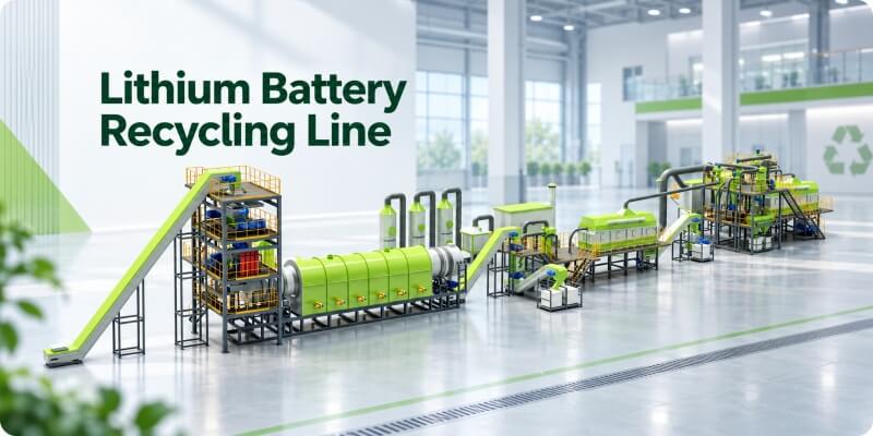
Stable silicon recovery depends on coordinated feed control, thermal delamination, staged crushing, and precise downstream separation. Therefore, project buyers should evaluate recovery rate, product purity, and reject-stream losses across the complete line. Yushunxin can design mixed-panel recycling solutions around your panel structure, capacity, site conditions, and target products. We can also integrate glass separation, metal recovery, silicon upgrading, and silver extraction. And if you want to recycle more e-waste, such as lithium battery recycling plant, waste tire pyrolysis line and waste plastic pyrolysis plant.
”
From Your Needs
to Real Impact


